DIY Arduino Based Home Monitoring System to Take Care of Elders
Home Safety Monitoring System – Arduino IoT Project that will monitor your Room’s environmental parameters like temperature, light, humidity and pressure as well as air quality.
While I waited for my flight, my thoughts turned to the people back home. Of all of them, it was those who were older that worried me most in this new stage of life—the time when work would take place remotely and from a distance. So far so good though: their house is well-protected thanks to COVID 19 filters installed around every opening through which air can pass (windows/doors). They are also comfortable with security cameras set up throughout their property as added protection against intruders or other potential dangers they might face at night while alone.
Why do we need a Smart Home Monitoring System?
The age of COVID 19 makes the quality of air crucial for ensuring that elders live comfortably and safely. This is why we have to make sure their environment has a suitable indoor climate too, especially since they are not physically present there themselves!
DIY Arduino Based Real Time Home Monitoring System
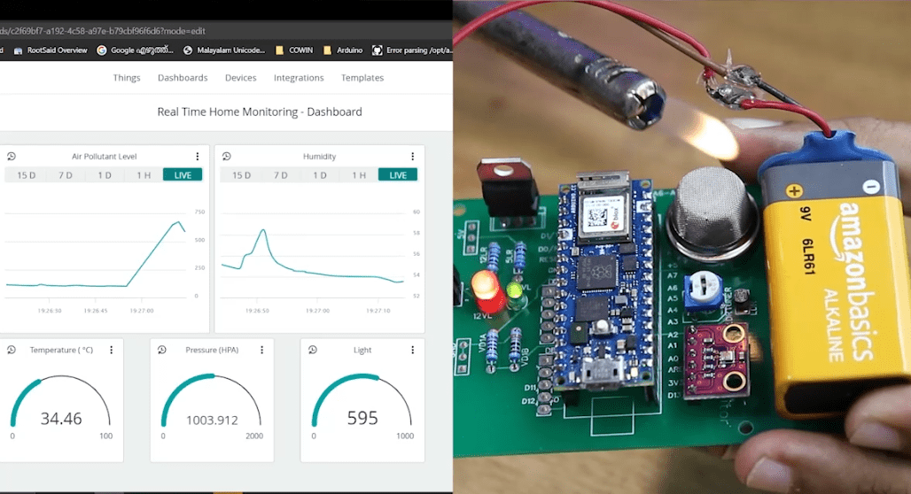
We made a device that can monitor the environmental conditions inside our homes like room temperature, air quality, humidity and ambient light. This helps us get instant alerts when something goes out of normal range.
In this tutorial, I will show you how to build your own DIY Arduino-powered real-time data dashboard. You’ll learn everything from the circuit design and layout all the way down to writing code for it!
In this tutorial, we’re going make our very own smart Internet of Things (IoT) device that can be used at home or in a professional setting such as an office space. We are also fortunate enough where there is already plenty of documentation online with instructions on building one yourself using off-the shelf parts so even if you have never done anything like this before but feel intrigued then read on because today’s post might just pique your interest further into figuring out what exactly IoT devices do and why they matter when trying
Components Needed
- Arduino Nano 33 IoT
- BME 280
- Gas sensor
- LDR
- Home safety monitor PCB
The reason why I chose Arduino Nano 33 IoT is, they are very small, pin to pin compatible with Arduino Nano r3 and it even has an inbuilt wifi module that will come in handy.
Learn Arduino the Easy Way
Are you new to Arduino? Do you want to improve your skills in Arduino programming? You are in the right place. We have a complete beginner-level tutorial for Arduino which covers everything from scratch. In this free Arduino Tutorial for Beginners guide, we will be taking a look at Introduction to Arduino platform, getting started with Arduino IDE, different types of Arduino boards, and a lot of DIY projects using Arduino. Check it Out!
Create your Own Home Monitoring System
Step 1 – Designing the Circuit
Let’s get started! I designed a circuit and PCB using Altium PCB Designer. It is great for designing complicated circuits, as well as multi-processor boards and industrial use cases. The link to the trial version will be in this description; definitely check it out if you’re interested!
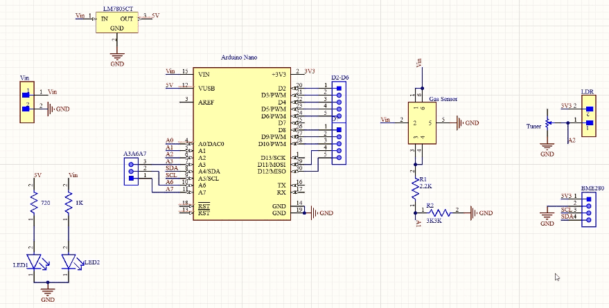
This is the circuit. Here we have Arduino Nano, a gas sensor, LDR, and a BME 280 sensor. This is the voltage input terminal, where we can connect a nine-volt battery or a 12-volt dc adapter. This 7805 voltage regulator will convert any voltage between 7 to 32 volt to a steady 5 volt supply. This 5v can be fed to Arduino and other components or if you are using Arduino Nano you can connect this Vin directly to the Vin pin of Arduino.
And then we have a gas sensor. There are different types of gas sensors depending on which gas you want to measure – there are methane sensors, carbon monoxide sensors, LPG sensors, you can choose the one depending on your needs. The output of the gas sensor is connected to pin a1 of Arduino.
Then we have an LDR. A trimmer is connected at this point so that we can adjust the sensitivity of this LDR and the output of LDR is connected to pin a2 of Arduino. The BME 280 is the sensor that we will be used to sense the temperature, humidity as well as pressure. The Vcc pin of BME 280 is connected to 3.3 volts of Arduino, the ground is connected to the ground, and SDA and SCL are connected to SDA and SCL Arduino. Basically, this is our circuit.
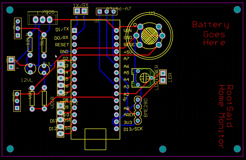
Once the circuit was finished and tested, I designed a compact PCB using Altium, where I can fix all the components neatly. Here you can see routing is on both sides of the board which means it is a dual-layer PCB. Now all I have to do is export the Gerber file.
Step 3 – Getting the PCB Done
Why not make a PCB for your Project?
Making a PCB for your DIY project is not hard nowadays. PCB helps to get rid of all messy wires and stuff and gives your project an awesome look. And it’s cool to make your own PCB for your project right?
I ordered PCB from PCBWay. PCBWay is a PCB manufacturer specializing in PCB prototyping, low-volume production, and neat and tidy PCB assembly.
To order your PCB from PCBWay, go to the PCBWay website and fill in the basic board details in the instant order form. From there you will be directed to a form where you can provide more elaborate board details. Update your board information in the PCB specification screen. On the next screen, you should be able to upload your Gerber file and submit it for review. Once the review is completed, all that is left is to add to the cart, make payment, and wait for your PCBs to arrive.
Once you get all the components and the PCB, it’s time for you to solder them together. Solder all the components onto the board and make sure to check the polarity of the components. After soldering the PCB looks like this.
Step 4 – The Software Part – Arduino IoT Cloud
Here we are in the Arduino IoT cloud. Here you can see I have already created a device called a real-time room condition monitoring system. So if we go inside that you can see five variables named humidity, light, value, oxygen value, pressure, and temperature, and here you can see I have already linked this project to this Arduino board RP 2040 which is my Arduino Nano RP 2040 and below that under the network tab.
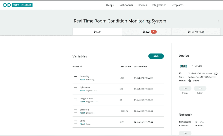
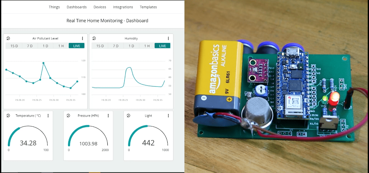
I have entered my WIFI SSID and password which the board will be using to connect to the internet and send all the values to Arduino IoT Cloud. Here we have a dashboard that will help us to visualize all the parameters.
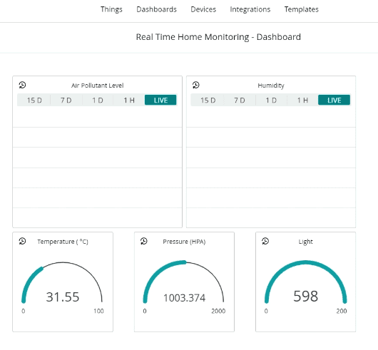
This is done by creating different panels for different variables and linking all the panels to the corresponding variables. If there is any change in temperature the value of the temperature changes and the gauge will change. The same goes for all the dashboards.
Step 5 – Alright, Lets Start Coding
Now we will start coding. The advantage of using Arduino IoT Cloud is once you have set up your thing and all the variables it will automatically generate a skeleton code that will include all the variables and critical functions which is required to run the code. We just have to add the extra variables and the functions.
#include "thingProperties.h"
#include <Adafruit_Sensor.h>
#include <Adafruit_BME280.h>
#define SEALEVELPRESSURE_HPA (1013.25)

Adafruit_BME280 bme;

int ledPin = 13;

void setup() {
  Serial.begin(9600);
  delay(1500);
  initProperties();
  ArduinoCloud.begin(ArduinoIoTPreferredConnection);
  setDebugMessageLevel(2);
  ArduinoCloud.printDebugInfo();

  bme.begin(0x76);
}

void loop() {
  ArduinoCloud.update();
  delay(1000);
  sensors();

}

void onHumidityChange() {
}

void onTempChange() {
}

void onAlertChange() {
}


void sensors() {
  lightValue = analogRead(A2);
  oxygenValue = analogRead(A1);
  pressure = bme.readPressure() / 100.0F;
  temp = bme.readTemperature();
  humidity = bme.readHumidity();


  Serial.print("Light = ");
  Serial.println(lightValue);
  Serial.print("Oxygen Level = ");
  Serial.println(oxygenValue);
  Serial.print("Temperature = ");
  Serial.println(temp);
  Serial.print("Humidity = ");
  Serial.println(humidity);
  Serial.print("Pressure = ");
  Serial.println(pressure);
  Serial.println("");

}
First, we’ll be adding all the libraries and declaring all the variables that we’ll be using in this project, which will help us to connect to Arduino IoT Cloud and communicate with BME280. Once it is done we will initialize the serial communication, communication with Arduino IoT Cloud, and then prepare the board to run the remaining code.
In the loop function, we are simply calling two other functions. The first function is sensors. In the functions of the sensor, we’ll fetch all the data from the sensors and store it in different variables and print these values and the Arduino Cloud. The update function will update all these variables onto the Cloud. Now you can simply upload this code onto your board. That was easy right. Now I will do the demo. Watch the demo video below
Lets Turn It On!
Now, let’s do a demo. See what happens when I blow onto the board, cover it with my finger, increase the ambient light, etc.
Awesome Arduino Projects you DONT WANNA MISS!
Here is a list of the creative Arduino Projects implementing newer sensors and boards, which can be followed easily and are really interesting to implement. Even if you are a beginner and just started learning Arduino based projects, following these tutorials will be easy. All of the below Arduino based projects are well-explained step by step, with detailed tutorials on how to get started from scratch.