I am getting so many questions from my friends and subscribers who are starting to build their own robots. Some of them are not able to follow everything I do. So lets rewind a little bit. This time, I decided to do something for the beginners who are starting their journey. In this post, I will show you how to build a simple four wheeled robot using
Arduino and control it using a joystick. This one is very easy to build and perfect for beginners to get started on robotics.
You Will Need
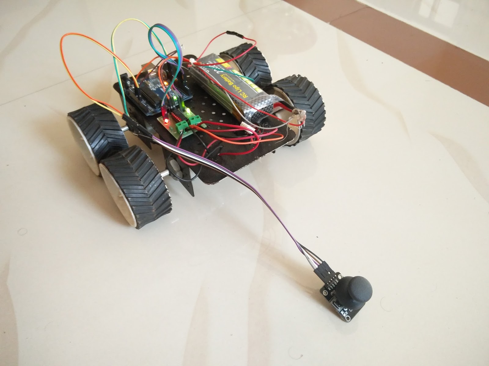
For this, you will need a chassis; a body to fix everything on, Four Wheels, Two Dummy Wheel Shafts, 2 DC motors, L293D Motor Driver,
Arduino UNO and a Battery.
Sponsor Link
This Project is Sponsored by
UTSource. UTSource is a professional electronic components supplier.
Get Started
In this Video Tutorial, I have explained each and everything in detail. Take a look at it. First take the chassis and fix the DC motors. Make sure the wheel won’t fall off while it is moving. You will have to tighten the nuts using a spanner. Now take the two dummy wheels shaft and fix it to the chassis. Now tighten all the connections using a spanner.
[AdSense-C] Next connect the wheels to all the four shafts. Take a wheel and insert the shaft into it. Now use a screw or a bolt to fix it. Do the same for all the four wheels. Now its time to fix our boards onto the body. Use some double sided tape to stick the boards on the body. First we will fix the
arduino. Then the motor driver….
The What??
H-Bridge motor Driver. This is the thing that is gonna drive our DC motors. Click here to know What is an H-Bridge Motor Driver? Read that? Now you know what an H-Bridge is. Now connect the terminals of the motor to the motor driver board. And fix the battery.
The Connections
The connections are easy.
[AdSense-B] I connected arduino and L293Ds Motor Driving Power Input Pin to 12 V lithium Polymer battery and connected the 5 V output of Arduino to the Motor Drivers VCC.
Connections from Arduino to L293D D3 ——> Input 1 of Motor A D4 ——> Input 2 of Motor A D6 ——> Input 1 of Motor B D7 ——> Input 2 of Motor B 5V ——> VCC of Motor Driver Board GND—-> GND of Motor Driver Board
Connections from Arduino to Joystick D13 —–> VCC of Joystick A0 ——> Output 1 of Joystick A1 ——> Output 2 of Joystick GND—–> GND of Joystick
Lets Start Writing
This is the code for moving the bot using the Joystick. Just copy all this and paste it inside arduino IDE.
[AdSense-B] void setup() { pinMode (3, OUTPUT); pinMode (13, OUTPUT); pinMode (4, OUTPUT); pinMode (6, OUTPUT); pinMode (7, OUTPUT); pinMode (A0, INPUT); pinMode (A1, INPUT); pinMode (A2, INPUT); Serial.begin(9600); } void forward() { digitalWrite(3, HIGH); digitalWrite(4, LOW); digitalWrite(6, HIGH); digitalWrite(7, LOW); } void backward() { digitalWrite(3, LOW); digitalWrite(4, HIGH); digitalWrite(6, LOW); digitalWrite(7, HIGH); } void left() { digitalWrite(3, HIGH); digitalWrite(4, LOW); digitalWrite(6, LOW); digitalWrite(7, HIGH); } void right() { digitalWrite(3, LOW); digitalWrite(4, HIGH); digitalWrite(6, HIGH); digitalWrite(7, LOW); } void stop() { digitalWrite(3, LOW); digitalWrite(4, LOW); digitalWrite(6, LOW); digitalWrite(7, LOW); } int fb,lr; void loop() { digitalWrite(13, HIGH); fb=analogRead(A0); lr=analogRead(A1); if (fb <= 50) { forward(); } else if (fb >= 900) { backward(); } else if (lr <= 50) { right(); } else if (lr >= 900) { left(); } else { stop(); } }
Upload the sketch and have fun.
View Comments
Howdy, May I grab that photo and usage it on my website?