DIY Science Project using Arduino – Time Catcher
In this Arduino DIY Science Project, I’ll show you how I created a time-keeping glove with just an Arduino, an accelerometer, and some LEDs. You can do this to make things appear to be frozen in time,…
In this Arduino DIY Science Project, I’ll show you how I created a time-keeping glove with just an Arduino, an accelerometer, and some LEDs. You can do this to make things appear to be frozen in time, as well as travel backward and forward in time by simply tilting your hands.
Here you can find complete information about the circuit, as well as PCB files if you want to create a PCB and complete the code. I’ll give you all the materials you need to redesign the whole thing, customise it, and then create your own edition. This project is extremely inexpensive, simple to complete, and will take you no more than 10 minutes to complete once you have all of the necessary components.
DIY Science Project using Arduino – Creating an Illusion using Arduino – Complete Video Tutorial
My name is Jithin, and I’m very excited to tell you everything you need to know about Arduino, Robotics, and other cool DIY hobbies. This channel is for you if you are a genuine Arduino enthusiast who is passionate about doing awesome DIY creations. So please subscribe to our channel by clicking here. Let’s get this project underway now.
Ordering PCB
I usually order our PCBs from PCBWay. PCBWay is a PCB manufacturer specializing in PCB prototyping, low-volume production, and neat and tidy PCB Assembly for a very low price. They have a very friendly customer support team and even perform a free PCB Design Review before payment and inform us if there is some issue with the design. Feel free to check out their website below.
How Time Catcher works?
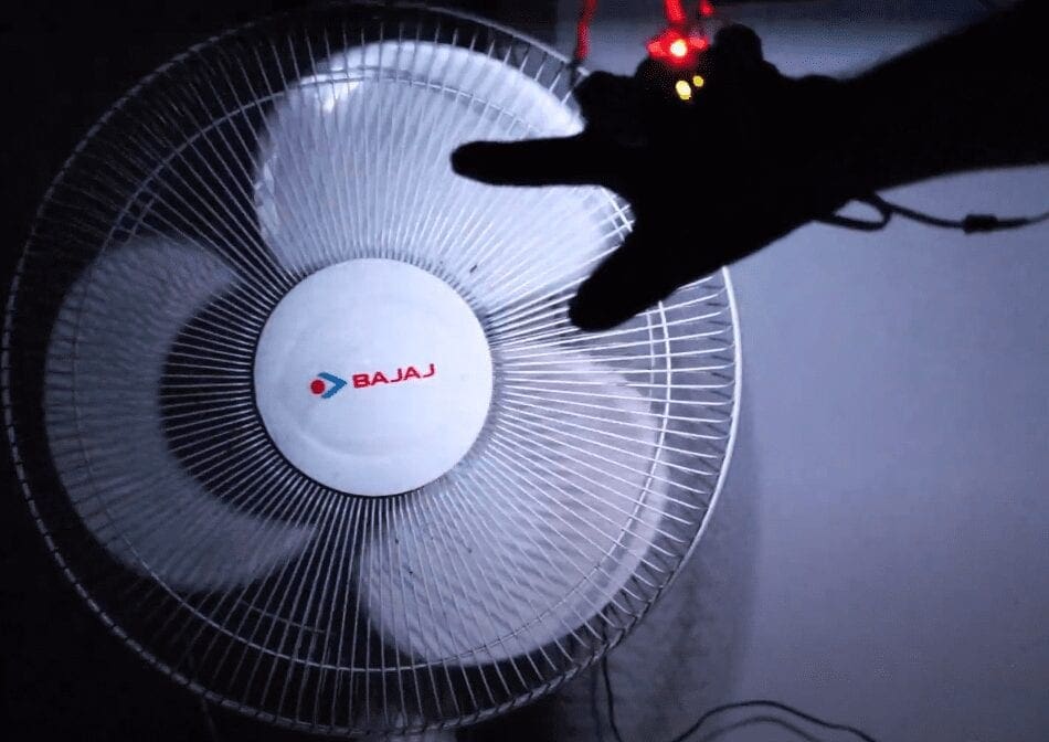
We create an illusion in this project, by blinking the lead in a certain frequency. The plan is to set the time limit that corresponds to everything that repeats itself.
For instance, when the blades come at a certain stage, in the case of this fan, we can blast this light. It’s like getting a glimpse of the object at a certain moment in time. If the frequency equals the frequency of the spinning fan, we can see the fan stop and sound as if it were stuck in time. If the frequency is increased, we can perceive the fan to be spinning backward.
DIY Science Project using Arduino – Components Needed
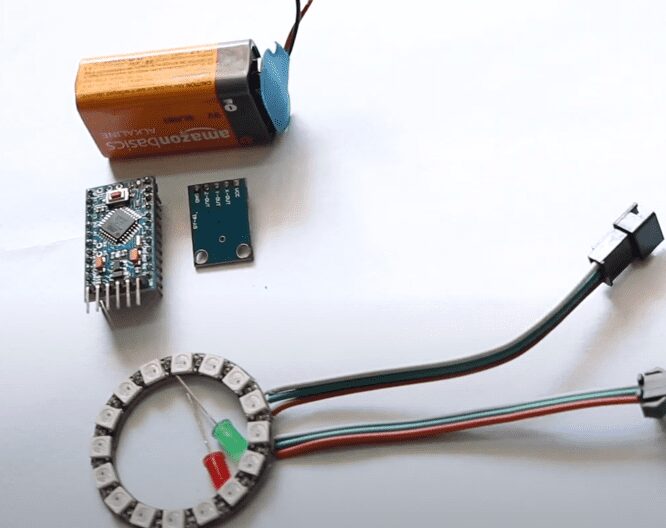
To do this project all I used was an
- Arduino
- Accelerometer
- Light source – I tried with some 5 volts LED and a Neopixel ring
- 9 Volt Battery
Basically, that’s all we need.
Step 1 – The Circuit
Let’s look at the circuit now. And here’s the designer of Altium. Here you can find an input terminal, Vin gloves, where a 9-volt battery, or DC power adapter can be connected. The input is connected to a 7805 voltage control system which converts an unregulated DC power supply from 7 to 32 volts. This 5V is then associated with the LED and the accelerometer of Arduino and the Indicator.
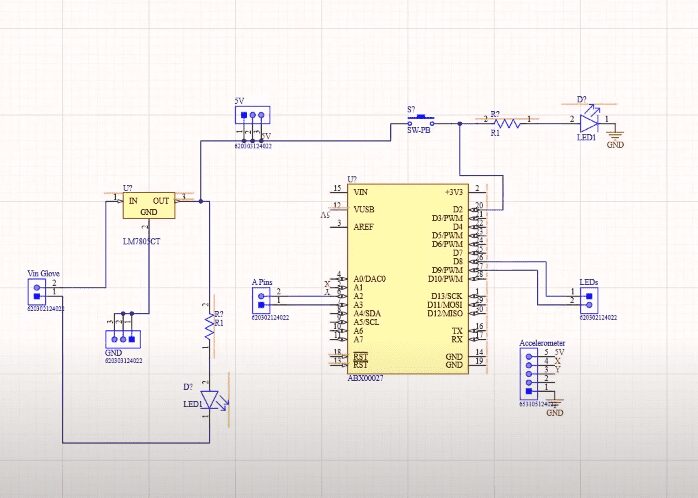
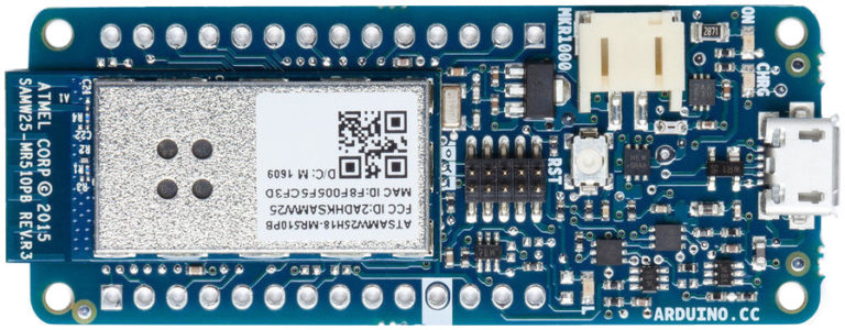
For this PCB, because of its limited size, I chose to go with Arduino Pro Mini. But for this project, you can naturally use any Arduino board. The IO pins 8 and 9 are wired to two terminals where the connection of some 5 V LEDs was planned. Anything I’ve been doing since I chose to go for Neopixel ring Pin 9. The accelerometer output X and Y is paired with Arduino’s analogue pins a0 and a1.
Certain headers in this PCB are linked to the Arduino analogue pins. This is because you can easily change flickering frequency without code if you attach a potentialometer to the analogue pins. And if you don’t use a potentiometer, it can work, but any time you try to alter it, it must be programmed to modify the frequency. That’s all I wanted for this project, essentially. If you intend to do so, try it on a breadboard, and you will be able to use it as such until the result is obtained, or create your own PCB.
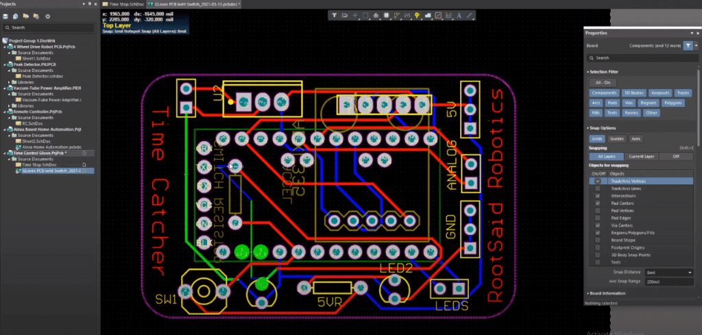
I like PCBs myself. PCBs are clean and help you get rid of all the wicked cables. And making your own PCBs correct for your project is great. In drawing the circuit and designing the PCB, I used Altium architecture. A versatile platform for designing and creating your own PCBs and complex and multiplayer PCBs for industrial applications, for your projects.
Step 2 – Ordering PCBs from PCBWay
I ordered my PCB from PCBWay. PCBWay is a PCB manufacturer specializing in PCB prototyping, low-volume production, and neat and tidy PCB Assembly.

To order your PCB from the PCBWay, Go to the PCBWay website and fill in the basic board details in the instant order form. From there you will be directed to a form where you can provide more elaborate board details. Update your board information in the PCB Specification screen. In the next screen, you should be able to upload your Gerber file and submit it for review. Once the review is completed, all that is left is to add to the cart, make the payment, and wait for your PCBs to arrive.
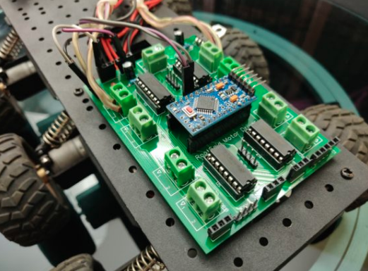
Once you get all the components and the PCB, it’s time for you to solder them together. Solder all the components onto the board and make sure to check the polarity of the components. After soldering the PCB looks like this.
Step 3 – Coding
Let’s look at the code now. Firstly, the libraries and header files to execute the code are to be named. I have to add his header files, pin setup and libraries to manage the neopixel ring as I use the neo-pixel library.
#include <Adafruit_NeoPixel.h>
#ifdef __AVR__
 #include <avr/power.h>
#endif
#define PIN        9
#define NUMPIXELS 16
Adafruit_NeoPixel pixels(NUMPIXELS, PIN, NEO_GRB + NEO_KHZ800);

int x,y,ontime,offtime;

void setup() {
#if defined(__AVR_ATtiny85__) && (F_CPU == 16000000)
  clock_prescale_set(clock_div_1);
#endif
  pixels.begin();
  Serial.begin(9600);

  lightnormal(); // Turn light ON for 5 minutes before it starts blinking
  delay(5000);
}

void loop() {

y=map(analogRead(A1), 250, 410, 10, 100);
Serial.print("Y = ");
Serial.println(y);

ontime = y/128;
offtime = y;
lightup();
}


void lightup()
{
  pixels.clear();
  pixels.show();
  delay(offtime);
  pixels.fill(pixels.Color(255, 255, 255), 0, 15);
  pixels.show();
  delay(ontime);

/* // Code for LED Connected to D9(If you are not using Neopixel Ring)
  digitalWrite(D9, HIGH);
  delay(ontime);
  digitalWrite(D9, LOW);
  delay(offtime);
  */
}

void lightnormal()
{
  pixels.fill(pixels.Color(120, 120, 120), 0, 15);
  pixels.show();

/* // Code for LED Connected to D9 (If you are not using Neopixel Ring)
  digitalWrite(D9, LOW);
  */

}
But if you have decided not to use neopixel LED ring and go with ordinary LED you won’t have to use any of these codes.
Code Explained
After that, we will declare 4 variables X, Y, ON time, and OFF time.
In the setup function, we will initialize the neopixel ring, start the serial communication and turn on the LED or ring for 5 seconds before it starts blinking.
void setup() {
#if defined(__AVR_ATtiny85__) && (F_CPU == 16000000)
  clock_prescale_set(clock_div_1);
#endif
  pixels.begin();
  Serial.begin(9600);

  lightnormal(); // Turn light ON for 5 minutes before it starts blinking
  delay(5000);
}
In the loop, the function will be taking the analog reading of pin A1 where the output of the accelerometer is connected, whose value varies from 250 to 410, and map that to a value between 10 and 100.
y=map(analogRead(A1), 250, 410, 10, 100);This value is then divided by 128 and stored in the variable on time and the value y is saved in the variable of time.
ontime = y/128;
offtime = y;
Now all I have to do is turn on and off the LED on the neopixel ring with the value of on-time and off-time as on an off delay.
In the light-up function, we will be turning on all the LED in the ring and wait for a duration of on time, which is usually a few milliseconds. After that, it will clear all the LEDs and wait for the duration of time. this whole thing repeats again and again.
void lightup()
{
  pixels.clear();
  pixels.show();
  delay(offtime);
  pixels.fill(pixels.Color(255, 255, 255), 0, 15);
  pixels.show();
  delay(ontime);

/* // Code for LED Connected to D9(If you are not using Neopixel Ring)
  digitalWrite(D9, HIGH);
  delay(ontime);
  digitalWrite(D9, LOW);
  delay(offtime);
  */
}
The only thing that changes is the on-time and off-time which is directly proportional to the value of the Y output of the accelerometer. That is how I changed the blinking frequency by tilting my hand.
The light normal function will turn on all the LEDs of neopixel ring.
Coding Tips for DIY Science Project using Arduino
And you can use these codes instead of this neopixel code If you are using an LED instead of neopixel ring.
The only adjustments we will have to make it in this section.
y=map(analogRead(A1), 250, 410, 10, 100);You can play around with these values and once you get to know the correct frequency you can finetune and adjust the values. at first, the on-time and off-time were set as y. but after so many trials I found out that it’s best to set the value of on-time as low as possible. setting it to a lower value as compared to time will give a sharper image.
Step 4 – Uploading the Code
The code is complete now you can select the right port and board and upload the code.
Step 5 – Assembling and Testing
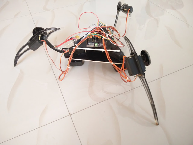
Now you can connect everything to the gloves. You can use a glue gun to fix the neopixel ring in the palm of the glove and the board and the battery on the backside of the gloves.
That’s it, guys. Our project is now done now you can turn it on and have fun with it.