Time Catcher – DIY Arduino Project – Creating an Illusion
Arduino DIY Project 2021 – How to make this time caching glove using just an Arduino, accelerometer, and some LED?
Story
In this DIY Science Project using Arduino, I am gonna show you how I made this time caching glove using just an Arduino, accelerometer, and some Led. Using this, you can make something look like it’s frozen in time, move backward and forward through time by simply tilting your hands.
DIY Arduino Project – Creating an Illusion
Here will be giving you complete details including the circuit, the PCB files if you want to make a PCB and complete the code. I will provide all the resources so that you can redesign the entire thing, customize it and then make your own version of it. This project is really cheap, very easy to make and once you have all the components it won’t take more than 10 minutes to make one yourself.
DIY Arduino Project – Creating an Illusion – Complete Video Tutorial
My name is Jithin and I’m super excited to teach you everything you need to know about Arduino, Robotics, and other fun DIY hobby projects. If you are a true fan of Arduino and you are really interested in building amazing DIY projects, then this channel is for you. So make sure you subscribe to our channel by hitting the subscribe button here. Now, let’s get started with the project.
Why not make a PCB for your Project?
Making a PCB for your DIY project is not hard nowadays. PCB helps to get rid of all messy wires and stuff and gives your project an awesome look. And its cool to make your own PCB for your project right?
Ordering PCB
I usually order our PCBs from PCBWay. PCBWay is a PCB manufacturer specializing in PCB prototyping, low-volume production, and neat and tidy PCB Assembly for a very low price. They have a very friendly customer support team and even perform a free PCB Design Review before payment and inform us if there is some issue with the design. Feel free to check out their website below.
Make your own PCB for your Project
How Time Catcher works?
In this project, we are actually creating an illusion by flashing the led in a particular frequency. The plan is to set the time period which is equal to something repeating itself.
For example in the case of this fan, we will be flashing this light whenever the blades come at a particular point. It is like taking a point in time snapshot of the object. If the frequency is equal to the frequency of the rotating fan, we will see the fan standing still and we will feel like it is frozen in time. If the frequency is a bit higher, we will feel like the fan is rotating backward. If the frequency is a bit lower we will feel like the fan is rotating forward. All you have to do is blink the LED with a frequency that is equal to or near the frequency of the object.
DIY Arduino Project – Creating an Illusion – Components Needed
To do this project all I used was –

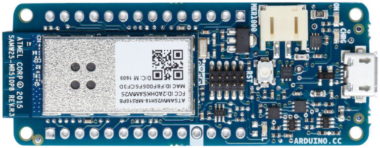
- Arduino
- Accelerometer
- Light source – I tried with some 5 volts LED and a Neopixel ring
- 9 Volt Battery
Basically, that’s all we need.
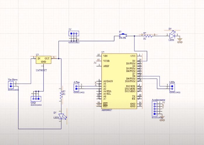
Step 1 – The Circuit
Now let’s take a look at the circuit. And here we are in Altium designer. Here you will see a voltage is input terminal, Vin gloves, where I can connect a 9-volt battery or a DC power adaptor. This voltage input is connected to a 7805 voltage regulator which will convert an unregulated DC voltage of 7 to 32 volt to 5 volt DC power supply. This 5 V is then connected to Arduino and Indicator LED as well as the accelerometer.
Get Complete Details about Circuit and PCB Layout from Arduino LED Projects Here.
I personally like PCBs. PCBs are neat and help to get rid of all nasty wires hanging around. And it’s cool to make your own PCBs for your project right. I used Altium designer to draw the circuit nd design the PCB. It is a powerful tool that can be used to design and create your own PCBs for your project as well as complex and multiplayer PCBs for industrial use.
Step 2 – Ordering PCBs from PCBWay
I ordered my PCB from PCBWay. PCBWay is a PCB manufacturer specializing in PCB prototyping, low-volume production, and neat and tidy PCB Assembly.

To order your PCB from the PCBWay, Go to the PCBWay website and fill in the basic board details in the instant order form. From there you will be directed to a form where you can provide more elaborate board details. Update your board information in the PCB Specification screen. In the next screen, you should be able to upload your Gerber file and submit it for review. Once the review is completed, all that is left is to add to the cart, make the payment, and wait for your PCBs to arrive.
Once you get all the components and the PCB, it’s time for you to solder them together. Solder all the components onto the board and make sure to check the polarity of the components. After soldering the PCB looks like this.

_sJcvyYDUfP.png?auto=compress%2Cformat&w=740&h=555&fit=max)
1 / 2
Step 3 – Coding
Now let’s take a look at the code. The first thing is to call the libraries and header files that are needed to run the code. Since I am using the neo pixel library I have to include its header files, pin configuration, as well as libraries to control the neopixel ring.

Get Complete Code for Arduino LED Projects Here.
But if you have decided not to use neopixel LED ring and go with ordinary LED you won’t have to use any of these codes.
Code Explained
After that, we will declare 4 variables X, Y, ON time, and of time.
In the setup function, we will initialize the neopixel ring, start the serial communication and turn on the LED or ring for 5 seconds before it starts blinking.
In the loop, the function will be taking the analog reading of pin A1 where the output of the accelerometer is connected, whose value varies from 250 to 410, and map that to a value between 10 and 100.
Now all I have to do is turn on and off the LED on the neopixel ring with the value of on-time and off-time as on an off delay.
In the light-up function, we will be turning on all the LED in the ring and wait for a duration of on time, which is usually a few milliseconds. After that, it will clear all the LEDs and wait for the duration of time. this whole thing repeats again and again.
The only thing that changes is the on-time and off-time which is directly proportional to the value of the Y output of the accelerometer. That is how I changed the blinking frequency by tilting my hand.
The light normal function will turn on all the LEDs of neopixel ring.
Coding Tips for Arduino LED Projects
And you can use these codes instead of this neopixel code If you are using an LED instead of neopixel ring.
The only adjustments we will have to make it in this section.
y=map(analogRead(A1), 250, 410, 10, 100);You can play around with these values and once you get to know the correct frequency you can finetune and adjust the values. at first, the on-time and off-time were set as y. but after so many trials I found out that it’s best to set the value of on-time as low as possible. setting it to a lower value as compared to time will give a sharper image.
Step 4 – Uploading the Code
The code is complete now you can select the right port and board and upload the code.
Step 5 – Assembling and Testing
Now you can connect everything to the gloves. You can use a glue gun to fix the neopixel ring in the palm of the glove and the board and the battery on the backside of the gloves.

That’s it, guys. Our Arduino LED Projects is now done now you can turn it on and have fun with it.