Arduino Object Tracking Robot!
Arduino AI Project – Object Tracking Robot
Hey, in the previous posts and videos of this Arduino AI Vision Sensor Tutorial series, I told you what a HuskyLens is, what you can do with it and how you can connect HuskyLens to Arduino. How about an Object Tracking Arduino Robot? Guys in this video, I will show you how you can make an Object Tracking Robot using Arduino. Stay tuned!

About Our Sponsor – PCBWay
This project is sponsored by PCBWay. PCBWay is a PCB manufacturer specializing in PCB prototyping, low-volume production and neat and tidy PCB Assembly. They deliver high-quality PCB faster and cheaper.

As one of the most experienced PCB manufacturers in China, they pride themselves to be our best business partners as well as good friends in the every aspect of your PCB needs.
Object Tracking Robot Video Tutorial
Components Needed to build Object Tracking Robot | Arduino AI Project
For this Object Tracking Robot Tutorial, you will need
- Arduino Pro Mini
- HuskyLens
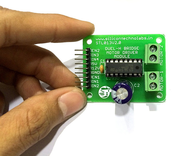
- L293D Motor Driver
- Robot Chassis
- Jumper Wires and Connecting Cables
Steps for Making Arduino Object Tracking Robot – Arduino AI Project
Step 1 – Designing the PCB
Guys, I have designed a PCB layout where you can easily mount your Arduino Pro Mini and L293D, set this up without using messy wires and cables hanging around.

The board is lightweight and can be powered using a 9V battery or a 9-12 V power adapter.

Step 2 – Ordering the PCB
Getting the PCB from PCBWay


To order your PCB from PCB way, Go to PCBWay and fill the board details in the instant order form.
From there you will be directed form where you can provide more elaborate board details and Gerber upload.
Update your board requirement information in the PCB Specification screen.

You can change the board thickness, board color, silk color, and even the type of finish you want. Some of these add-ons are going to increase the board cost.


Once you have all of the various options for your PCB selected, submit it for review. Before your board goes into manufacturing their team of professional technicians will review your design for any potential errors.
Once the review is completed, all that is left is to add to cart, make payment, and wait for your PCBs to arrive. It could take anywhere from 3 – to 6 days to be produced depending on the number of boards you ordered.

Soldering
Once you get all the components, it’s time for you to solder them together. Solder all the components onto the board and make sure to check the polarity of the components.
Step 4 – Setting up the Robot Chassis
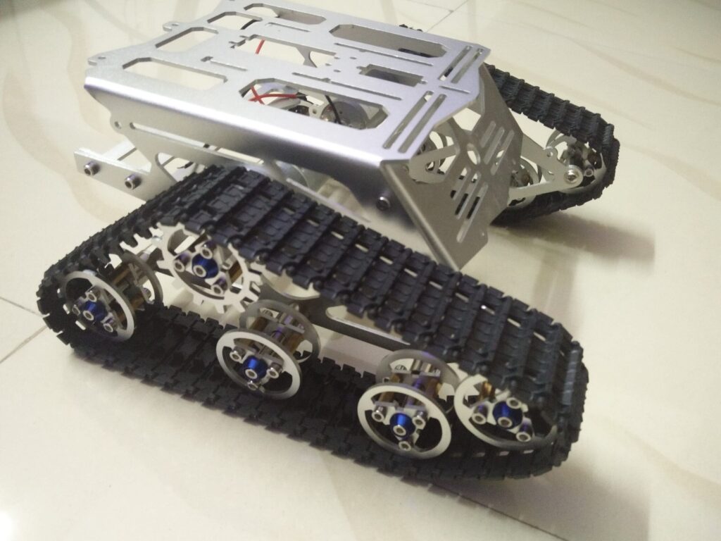
Now, we need a robot chassis. This one I have is one of the best chassis I use to built Spinel Crux. If you want this, I will leave the link in the description. Go check it out!
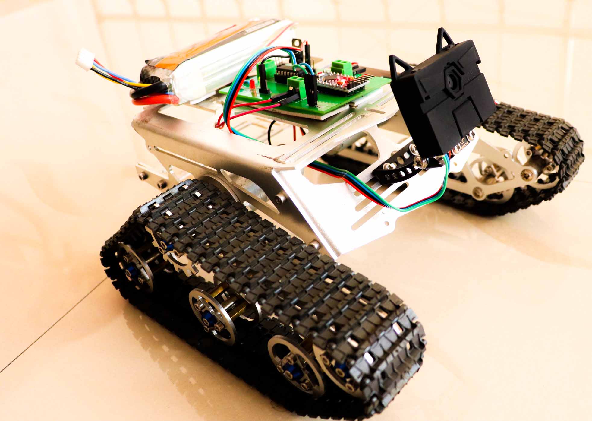
You can use the mounting brackets and pieces that come with the HuskyLens camera to attach it to the chassis.

Once you attach the HuskyLens to the chassis, you can fix the assembled PCB and battery on top of the chassis.
Step 3 – Installing Arduino Library for HuskyLens
Next thing we wanna do is install HuskyLens Library for Arduino. In the below video, I have explained all the steps inorder to install HuskyLens from Arduino IDE Download to first code upload. Check that out!
Step 4 – Coding
Now its time to code. In the previous video, I showed you how to upload basic code to Arduino and Read HuskyLens data from it. Check out the above video if you wanna know more about integrating Hukylens to Arduino.
Click Here to download the code.
#include "HUSKYLENS.h"
#include "SoftwareSerial.h"

HUSKYLENS huskylens;
SoftwareSerial mySerial(10, 11);
int ledPin = 13;
void printResult(HUSKYLENSResult result);

void setup() {
    Serial.begin(115200);
    mySerial.begin(9600);
    pinMode (2, OUTPUT);
    pinMode (3, OUTPUT);
    pinMode (4, OUTPUT);
    pinMode (7, OUTPUT);
    pinMode (5, OUTPUT);
    pinMode (6, OUTPUT);
    pinMode(ledPin, OUTPUT);

    analogWrite(5, 180); //motor1 enable pin
    analogWrite(6, 180); //motor2 enable pin

    while (!huskylens.begin(mySerial))
    {
        Serial.println(F("Begin failed!"));
        Serial.println(F("1.Please recheck the \"Protocol Type\" in HUSKYLENS (General Settings>>Protocol Type>>Serial 9600)"));
        Serial.println(F("2.Please recheck the connection."));
        delay(100);
    }
}

void loop()
{
    if (!huskylens.request())
Serial.println(F("Fail to request data from HUSKYLENS, recheck the connection!"));

    else if(!huskylens.isLearned())
Serial.println(F("Nothing learned, press learn button on HUSKYLENS to learn one!"));

    else if(!huskylens.available())
Serial.println(F("No block or arrow appears on the screen!"));

    else
    {
        Serial.println(F("###########"));
        while (huskylens.available())
        {
            HUSKYLENSResult result = huskylens.read();
            printResult(result);
            driveBot(result);
        }
    }
}


void printResult(HUSKYLENSResult result){
    if (result.command == COMMAND_RETURN_BLOCK){
        Serial.println(String()+F("Block:xCenter=")+result.xCenter+F(",yCenter=")+result.yCenter+F(",width=")+result.width+F(",height=")+result.height+F(",ID=")+result.ID);
    }
    else if (result.command == COMMAND_RETURN_ARROW){
        Serial.println(String()+F("Arrow:xOrigin=")+result.xOrigin+F(",yOrigin=")+result.yOrigin+F(",xTarget=")+result.xTarget+F(",yTarget=")+result.yTarget+F(",ID=")+result.ID);
    }
    else{
        Serial.println("Object unknown!");
    }
}

void driveBot(HUSKYLENSResult result)
{
  if(result.xCenter<=140)
  {
    left();
  }

  else if(result.xCenter>=200)
  {
    right();
  }

    else if((result.xCenter>=140)&&(result.xCenter<=200))
  {
    if(result.width<=20)
    {
      forward();
    }

    else if(result.width>20)
    {
      stop();
    }
  }

}


void stop()
{
digitalWrite(2, LOW);
digitalWrite(3, LOW);
digitalWrite(7, LOW);
digitalWrite(4, LOW);
digitalWrite(ledPin, LOW);
Serial.println("Stop");
}
void right()
{
digitalWrite(2, HIGH);
digitalWrite(3, LOW);
digitalWrite(7, LOW);
digitalWrite(4, HIGH);
digitalWrite(ledPin, HIGH);
Serial.println(" Rotate Right");
}
void left()
{
digitalWrite(2, LOW);
digitalWrite(3, HIGH);
digitalWrite(7, HIGH);
digitalWrite(4, LOW);
digitalWrite(ledPin, HIGH);
Serial.println(" Rotate Left");
}

void forward()
{
digitalWrite(2, LOW);
digitalWrite(3, HIGH);
digitalWrite(7, LOW);
digitalWrite(4, HIGH);
digitalWrite(ledPin, HIGH);
Serial.println("Forward");
}

void backward()
{
digitalWrite(2, HIGH);
digitalWrite(3, LOW);
digitalWrite(7, HIGH);
digitalWrite(4, LOW);
digitalWrite(ledPin, HIGH);
Serial.println("Forward");
}
Even though the code is lengthy, its very simple to understand. First we setup the Software serial library which will add an additional serial interface to arduino at pin 10 and 11 where we connect the HuskyLens.
Then we initiate both Serial interface at provided baudrate. Then we set the pin for driving the motors including the enable pins.
Then down the program, you will see some functions to drive the motor as well as displaying the Huskylens output that are read by Arduino.
Step 5 – Test Run
How about a test run? Now power on the bot and train an object by setting the Huskylens in Object tracking mode.

Once it is done, you can move the object left or right and the bot will start to follow the object.
Whats Next?
Now you know how to build an Object Tracking Robot using Arduino and HuskyLens. How about a face detection Robot? In the next post, we will go with a face recognition bot that will follow your face. Click on the subscribe if you want more cool projects.
New to Robotics?
We have a beginners guide on “Getting Started with Robotics” which will give you a kick start in this field. Check out our free video tutorial below for a brief introduction.
Did you find this page useful? Help us to improve by rating this page.
[RICH_REVIEWS_FORM]
[RICH_REVIEWS_SNIPPET stars_only=”true”]
![[Solved] Unable to locate package linux-headers | How to Install Kali 2020 Headers | Install Virtual Box](https://hackersgrid.com/wp-content/uploads/sites/5/2017/08/kali-wallpaper-2015-v1.1.0-1.jpg)
