Digispark Based Burglar Alarm with PCB Layout
Hey guys, welcome back, In the previous post, I told you how an IR sensor works, how to make a line follower using an IR sensor and to make a Simple DIY Burglar Alarm using an IR sensor and a Buzzer without using any micro controller or complicated coding.

In this Post, I will show you how to make a Simple PIR Burglar Alarm using Digispark.
PIR Burglar Alarm using Digispark Components Needed
To set this up, All you need is
- PIR sensor
- Digispark
- Buzzer
- Header Pins
- 9-12 Volt Power Adapter
DIY Burglar Alarm Tutorial
Digispark
Digispark is a new light weight micro-controller development board. Digispark comes with 6 GPIO pins, I2C and SPI serial communication and a USB interface.

It also has 3 PWM pins which can be used to control l293d motor drivers or servo motors. we can use arduino IDE to program digispark but the way we upload the program is a little bit different than usual arduino.
Learn more about Digispark and how to set it up with Arduino IDE from here.
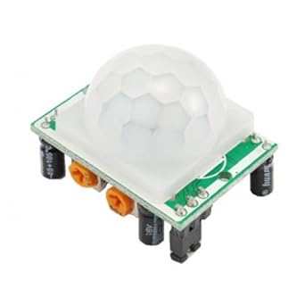
What is a PIR Sensor?
A PIR sensor is a tiny circuit that can detect human being moving around infront of it with in a range of range is between 4 Meter and 13 Meter.

PIR sensors are small, compact, and need minimal effort to set up with any project. They also have a wide lens range, and are very easy to interface with.
PIR Sensor Pinout
There are mainly 3 pins to PIR Sensor –
- VCC – Where we connect 5 V Power Supply
- Out – Output Voltage (5V when it detects human IR Signature)
- GND – Where we connect -ve Terminal
Online PCB Manufacturer – JLCPCB
JLCPCB is one of the best Online PCB manufacturing company from where you can order PCBs online without any hassle. The company works 24 hours a day, 7 days a week nonstop. With their high tech machinery and automated work stream, they can manufacture huge quantities of high-class PCBs within hours.

JLCPCB can develop PCBs of various complexity. They develop Simple and cheap PCBs with Single layer board for hobbyists and enthusiasts as well as complex multi layer board for high standard industrial applications. JLC works with large product manufacturers and may be the PCB of devices you are using such as laptop or mobile phones were made at this factory.
DIY Burglar Alarm
So Now you know how an IR sensor works. We will start building our Burglar alarm.
This project is very simple. You wont need more than 1 minute to set this up. This is how we set up the entire circuit.
Connections – Burglar Alarm Circuit
The Circuit
This is a simple circuit comprising of a PIR Sensor. The input power is connected to a 7805 regulator. 7805 is a 5V regulator which will convert an input voltage of 7- 32V to a steady 5V DC supply. So, you can connect an input voltage of anywhere between 7V to 32 to this circuit. For my bot, I prefer a 11.1V Lipo Battery. There are indicator LEDs across various points for easy troubleshooting.

To get Started, First Go to EasyEDA website and create a free account. Go to “Editor” and create a new project. For now, JLCPCB have 689 Basic components and 30k+ Extended components at your disposal. See the complete list of components here.
Make sure you add the components from this list while drawing the schematics in EasyEDA. You can even search for the components and check its availability. Now you can get your layout done using inbuilt tools in EasyEDA.

You can now download the Gerber file and use it to manufacture your PCB from JLCPCB. Gerber File contains information about your PCB such as PCB layout information, Layer information, spacing information, tracks to name a few. BOM File or Bill Of Material contains the list of all components in the Layout. CPL file(Component Placement List / Pick & Place File (PNP) file), it is used by automated SMT Assembly machines to determine where each part should be located on the board.
JLCPCB PCB Ordering
Go to JLCPCBs website and Click on “Quote Now” and upload your Gerber File.
Once the Gerber file is uploaded, it will show you a preview of your circuit board. Make sure this is the PCB Layout of the board you want.
Below the PCB preview, you will see so many options such as PCB Quantity, Texture, Thickness, Color etc. Choose all that are necessary for you. Click on “Assemble your PCB boards”.

Now, you will have to upload the BOM and CPL file that we downloaded earlier.

Select all the components you want JLCPCB to assemble in your PCB. Simply click on the confirm box to select the components.
In this page, you can review your order. You can check the layout, see all the components and if there is any problem, you can click on “Go Back” to edit your order.
Once everything is done, click on “Save To Cart”. In the next page, you can choose a shipping and payment option and Check Out Securely. You can either use Paypal or Credit/Debit Card to pay.
The PCB will be manufactured and shipped within days and will be delivered to your doorstep within the mentioned time period.
Once you get the PCB in hand, all you have to do is solder the header pins and connect the PIR Sensor.
The Code
We can now upload our code to Digispark. If you dont know how to set up Digispark, check out the video below.
This is the code for PIR Burglar Alarm using PIR Sensor-
void setup()
{
pinMode(0, INPUT);
pinMode(4, OUTPUT);//LED
pinMode(2, OUTPUT);//buzzer
pinMode(3, OUTPUT);//relay
pinMode(1, OUTPUT);//inbuild LED
}

void loop()
{

int pir=digitalRead(0);
if(pir==1)
{
digitalWrite(4, HIGH);
digitalWrite(2, HIGH);
digitalWrite(3, HIGH);
digitalWrite(1, HIGH);
delay(500);
digitalWrite(6, LOW);
digitalWrite(2, LOW);
digitalWrite(3, LOW);
digitalWrite(1, LOW);
delay(200);
}

else
{
digitalWrite(6, LOW);
digitalWrite(2, LOW);
digitalWrite(3, LOW);
digitalWrite(1, LOW);
delay(1000);
}
}
Burglar Alarm Working Explained
Once it is done, connect the power adapter and you will see LED1 will glow up. This means it is working. Now you can use a jumper to shot both the terminals of the ‘Speaker’ which will close the circuit to the speaker (refer the circuit above). You will see the LED starts to glow and the buzzer will starts to beep for some time.

Now you can fix this somewhere in your room. When someone enters the room, it will starts to beep.
New to Robotics?
We have a beginners guide on “Getting Started with Robotics” which will give you a kick start in this field. Check out our free video tutorial below for a brief introduction.
Top Arduino Projects You can Try this Summer Vacation
Top Robotics Projects You can Try this Summer Vacation
Did you find this page useful? Help us to improve by rating this page.
[RICH_REVIEWS_FORM]
[RICH_REVIEWS_SNIPPET stars_only=”true”]


