DIY Photoshop Editing Console using Arduino Nano RP 2040 | Easier than you Think!
DIY Photoshop editing Console using Arduino Nano RP 2040 – In this Arduino HID project, I will be showing you can use an Arduino as a HID to send Photoshop shortcuts to your computer and edit photos easily.
Making a DIY Pohotoshop Editing Console
What if there was something that we could use to quickly change or swap between the tools in Adobe Photoshop with just one button push? Or, say you’re editing video clips and want more control over your brush size – what then. You all know what photoshop is right? It’s software used for digital image manipulation! There are lots of options within it which give us greater flexibility when working on our projects.
One way I like doing this though is by using keyboard shortcuts instead since they make accessing different functions easier than clicking through menus every time. Keyboard shortcuts are a common and effective way of saving time when working on your computer. When you use the right combinations, they can be even more efficient than using different tools because some functions might already exist in shortcut form instead!
What is HID?
This can be used as an input device for keyboards or mice, and by pressing certain key combinations it enables different tools. We will make use of this functionality in our project where we want to swap between multiple programs with just one button press!
The Circuit – DIY Photo Editing Console
Technology is all around us, and the world of electronics has come to be an integral part. I was never one for playing with wires as a child; instead, my creativity would go towards building things out of Legos or painting pictures on paper bags! But now that I’m grown up…well let me just say it’s time for some serious science-y goodness (ha)!
I used Altium Designer (an awesome tool)to create this circuit board design which allows users like myself more creative freedom than ever before when making their project plans happen – plus there are complex multiplayer boards too if you’re into industrial levels. If this sounds interesting give it try out with its 30% discount via the link below–you’ll thank me later 🙂
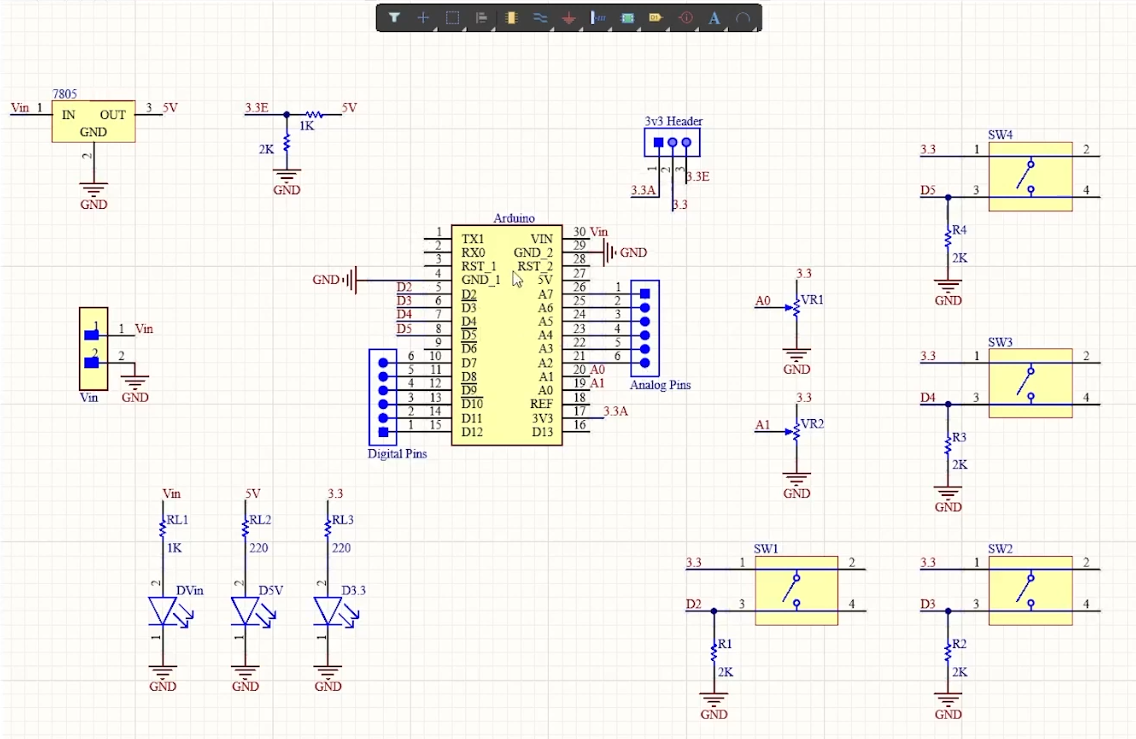
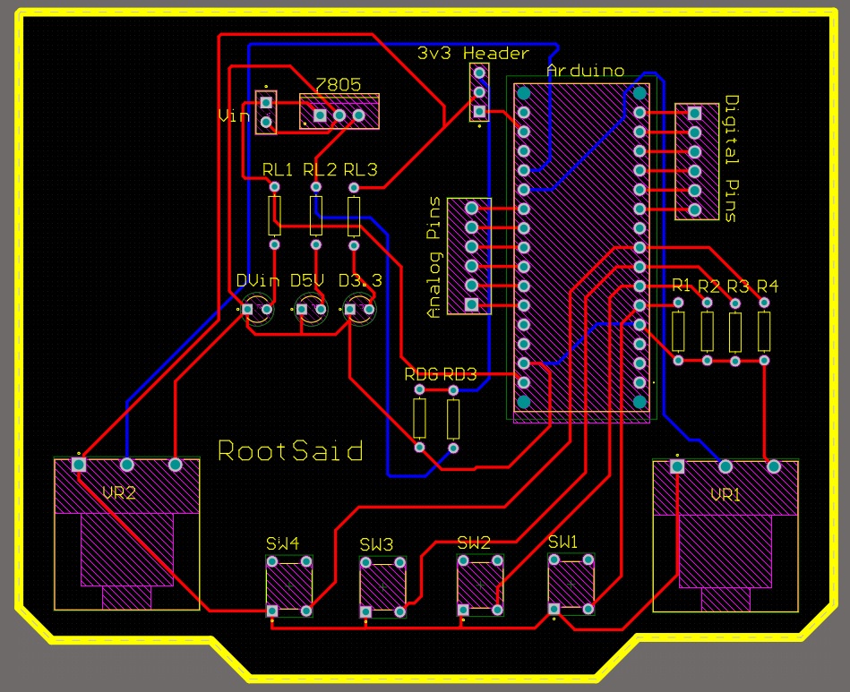
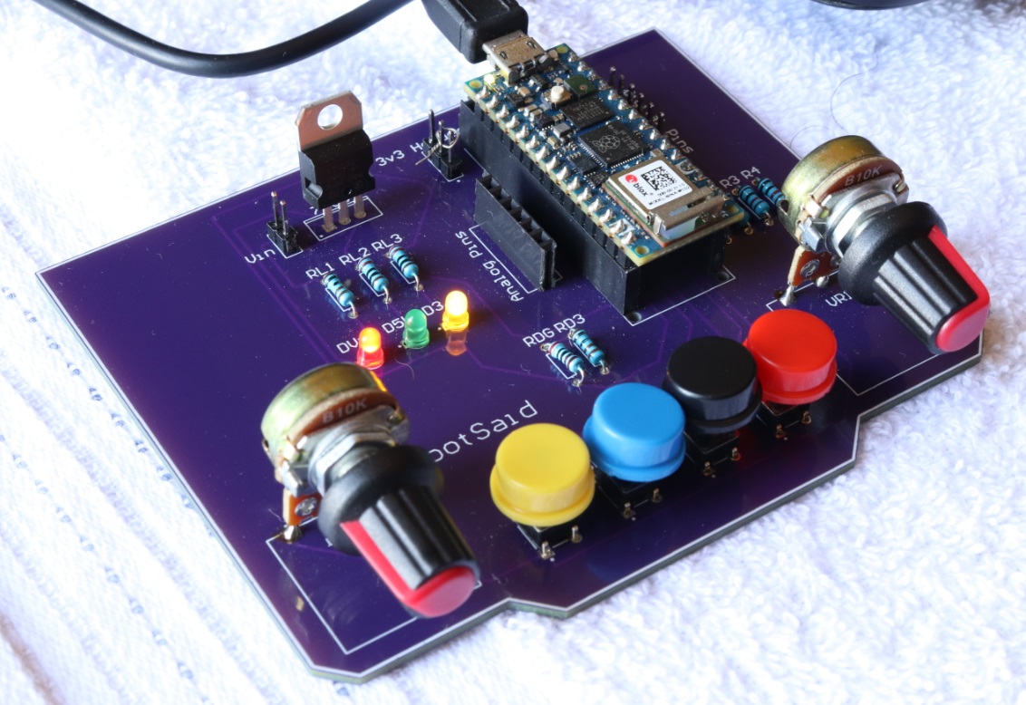
This project is a steering wheel. It has an Arduino Nano, which powers the brain of this system and connects to four pushbuttons from D2 through D5 on its digital pins 2-5; potentiometers assigned as analog ports A0 (blue) and A1(red), indicator LEDs strategically placed around it that will light up in accordance with certain key combinations being pressed by way or inputs into variables at different stages throughout coding process while powering other components delicately powered externally either via USB cable used solely if necessary–or else drawing power directly off USB.
This header will let you easily switch between the two voltage sources. The reason why I’m converting from 5V to 3.3 volts is that that’s what Arduino Nano RP 2040 operates at, and providing a higher voltage than its limits could fry my chip!
I designed this PCB using Altium where all components can be fixed neatly on both sides of one board making it a dual-layered product too.
Getting the PCB Done!
I ordered a PCB from PCBway. I am so happy because it’s easy and fast! They are a batch production-focused manufacturer that builds high-quality low-volume boards for prototyping or even one-time use only products with neat aesthetic assembly routines, like this order of mine!
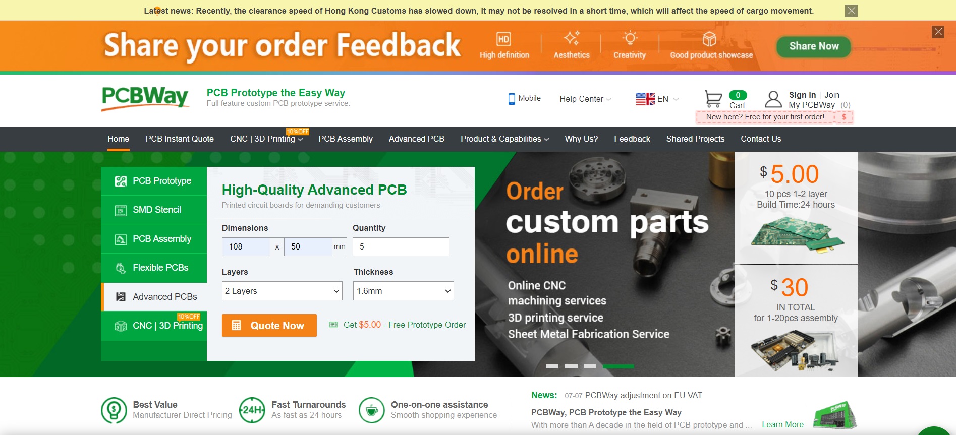
The process is really simple: go to the website, fill in basic information about my board design like size or function then upload Gerber files for review when fTo orders your PCB from PCBWay, go to the PCBWay website and fill in the basic board details in the instant order form. From there you will be directed to a form where you can provide more elaborate board details. Update your board information in the PCB specification screen. On the next screen, you should be able to upload your Gerber file and submit it for review. Once the review is completed, all that is left is to add to the cart, make payment, and wait for your PCBs to arrive.
Coding the Arduino Nano RP 2040
Now start the Arduino IDE and make sure you have installed Arduino Nano RP 2040 as well as USBHID library.
#include <PluggableUSBHID.h>
#include <USBKeyboard.h>

const int buttonPin1 = 2;
const int buttonPin2 = 3;
const int buttonPin3 = 4;
const int buttonPin4 = 5;
const int ledPin =  13;

USBKeyboard Keyboard;

int button1State = 0;
int button2State = 0;
int button3State = 0;
int button4State = 0;
int pot1 = 0;
int pot2 = 0;

void setup() {

  pinMode(ledPin, OUTPUT);
  pinMode(buttonPin1, INPUT);
  pinMode(buttonPin2, INPUT);
  pinMode(buttonPin3, INPUT);
  pinMode(buttonPin4, INPUT);
  pinMode(A0, INPUT);
  pinMode(A1, INPUT);

  Serial.begin(9600);
}

void loop() {
  button1State = digitalRead(buttonPin1);
  button2State = digitalRead(buttonPin2);
  button3State = digitalRead(buttonPin3);
  button4State = digitalRead(buttonPin4);
  pot1 = analogRead(A0);
  pot2 = analogRead(A1);

if (button1State == HIGH) {
    digitalWrite(ledPin, HIGH);
    Serial.println("Button 1 Pressed");
    Keyboard.key_code('t', KEY_CTRL); //Resize
    delay(500);
  } else {
    digitalWrite(ledPin, LOW);
  }

if (button2State == HIGH) {
    digitalWrite(ledPin, HIGH);
    delay(500);
    Serial.println("Button 2 Pressed");
    Keyboard.key_code('u', KEY_CTRL); //Press CTRL, u
  } else {
    digitalWrite(ledPin, LOW);
  }

if (button3State == HIGH) {
    digitalWrite(ledPin, HIGH);
    delay(500);
    Serial.println("Button 3 Pressed");
    Keyboard.key_code('j', KEY_CTRL); //Press J
  } else {
    digitalWrite(ledPin, LOW);
  }

if (button4State == HIGH) {
    digitalWrite(ledPin, HIGH);
    Keyboard.key_code('v'); //Press V
    delay(500);
    Serial.println("Button 4 Pressed");
  } else {
    digitalWrite(ledPin, LOW);
  }


if ((pot1>=750)&&(pot1<=400))
{
  Serial.println("Pot 1 Min"); // No Change
}
else if (pot1>750)
{
  Keyboard.key_code('-', KEY_CTRL); //Zoom Out
  delay(500);
}
else if (pot1<=400)
{
  Keyboard.key_code('+', KEY_CTRL); //Zoom In
  delay(500);
}

}
First, we will include the necessary header files. Now let’s initialize all of our variables so they are ready for use in the setup function. We’ll also need to set up serial communication when calling this function as well! Once everything is initialized correctly – including pins being assigned their modes. We can go to the loop function.
The next part is the action, and it’s entirely up to you. You can customize how you want your configuration! But I will show of course how my PC was configured; with buttons that respond only if they are pressed (like on an old-school Gameboy), two potentiometers like send Keystrokes when hit – or whatever else might suit your fancy really well too 😉
For example, if I press button1 it will send “ctrl+t” which is useful for resizing an image on the screen with one quick motion; pressing pot2 right makes me zoom into my canvas while turning left causes that same behavior when zooming outwards instead (note: there’s also a third option called panning). It works in much more ways than this too!
With the button, you can do a whole range of things. You could press and hold for one thing or two depending on how long you want to keep it pressed down- like I said it’s entirely up to your convenience!
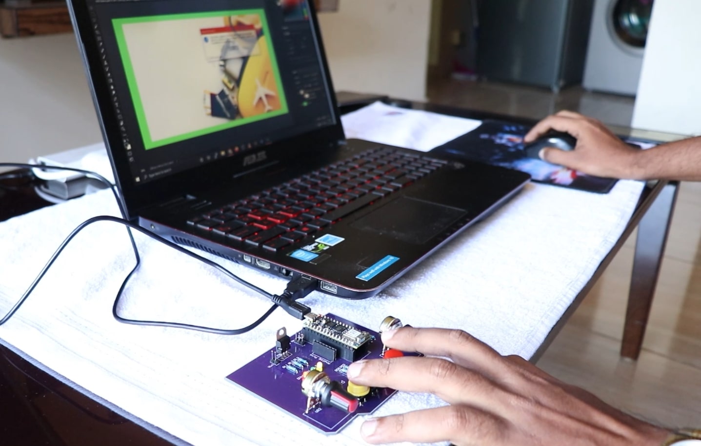
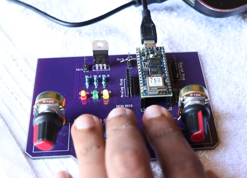
Now all you have to do is connect the Arduino board, fire up Photoshop or Premiere and try pressing any of its buttons. Once this becomes no longer challenging for your skillset then I’m sure there will be nothing else left worth talking about!
Testing
Now that everything has been tested (to make little sense), now comes a time where we need a proper test subject-in other words someone who can actually use what they just learned from getting beat down by our tutorial so hard their face hurts… right? Luckily enough though I found myself paired with somebody perfect beforehand

![[Solved] Unable to locate package linux-headers | How to Install Kali 2020 Headers | Install Virtual Box](https://hackersgrid.com/wp-content/uploads/2017/08/kali-wallpaper-2015-v1.1.0-1.jpg)