Make a Wireless Programmer for Classic Arduino Nano using HC05 Module
How to make a Wireless Programmer Shield for your Arduino Board and Bluetooth module.As always, you will receive complete instructions including the circuit diagram, the PCB files and codes to produce a PCB for yourself. Why do…
How to make a Wireless Programmer Shield for your Arduino Board and Bluetooth module.As always, you will receive complete instructions including the circuit diagram, the PCB files and codes to produce a PCB for yourself.
Why do we need a Wireless Programmer?
Usually, when we need to update the code running Arduino, we would have to remove the board from the circuit or PCB, connect it to a computer via USB, upload the code, and then re-attach the board to the circuit or PCB.
This Uploader eliminates the need to remove the circuit board from the PCB or circuit board. A USB cable is not even required to upload the code. Simply wirelessly upload the code whenever you like using a laptop or a desktop. OTA Code Upload or Over the Air Code Upload is what this is called.
Details for Bluetooth Module HC05
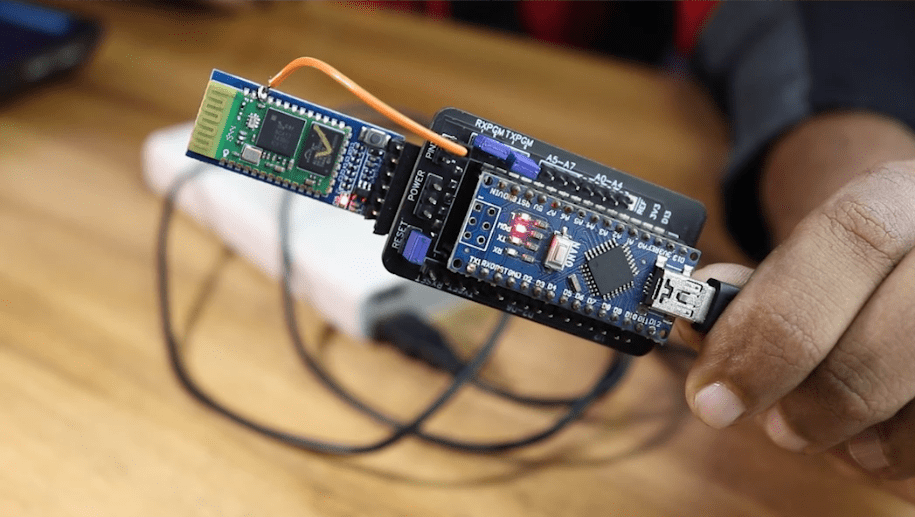
Bluetooth module HC-05 is used in this project. In addition to being inexpensive, it is also one of the most commonly used modules in many other projects. You should be able to obtain one from Amazon or eBay.com with little difficulty.
A wireless code uploader for Arduino : How did I make it?
This project will be divided into two stages.
- The Bluetooth module must be configured as the first step in the process.
- Wireless code upload is the second step.
The circuit of the first and second parts differs by a small amount. If you use the PCB I designed, you can easily change the connection using jumpers on the PCB itself. Using jumper cables is an easy way to set this up if you are using breadboards.
Making the Wireless Programmer Shield – Behind the Scenes
Circuit Design
I have designed a circuit that will allow us to connect the Arduino and Bluetooth module and do the configuration and wireless code upload without having to disconnect the Arduino and Bluetooth module.
For circuit design and PCB layout, I used Altium Designer. You can design and create your own PCBs for your project, as well as complex and multi-layer PCBs for industrial use, with this powerful tool. In the description, I’ll include a link to the free version. Check it out!
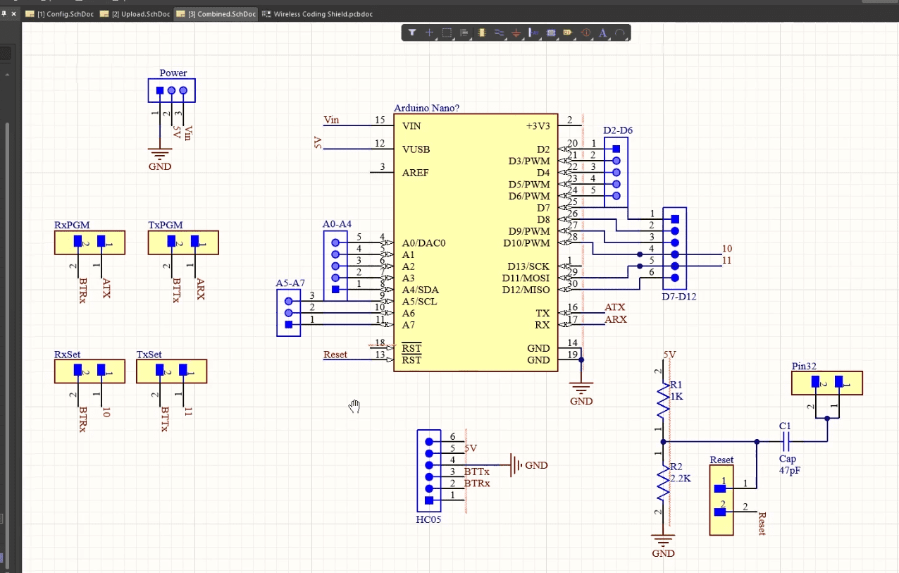
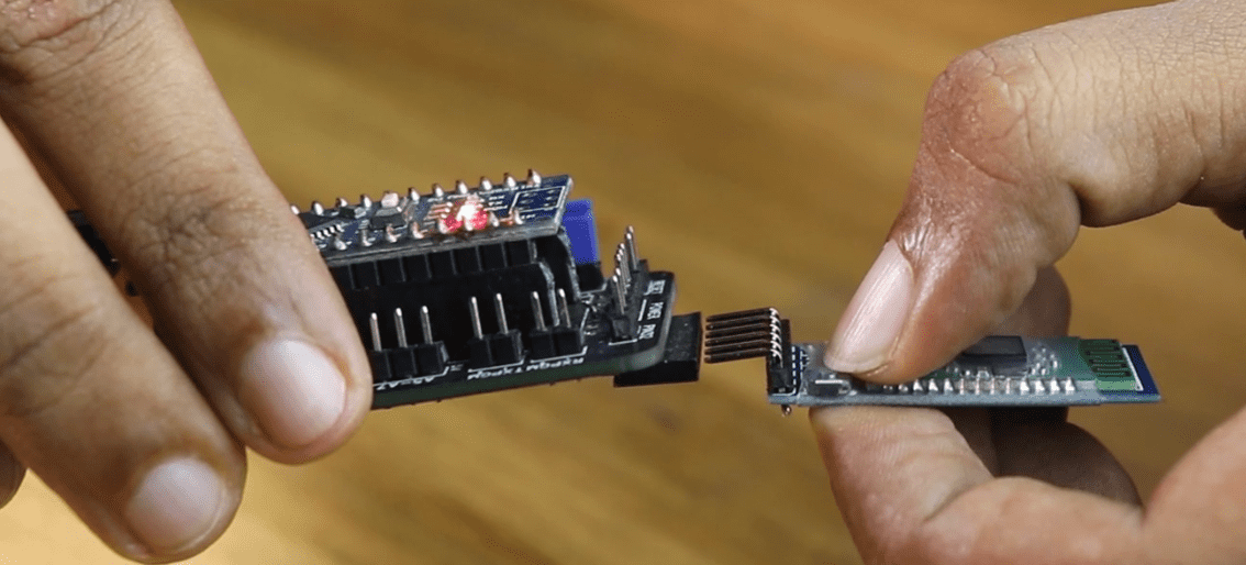
Actually, this PCB will serve as a shield for the nano-based Arduino. The Bluetooth module can be attached to the shield. Almost all of the digital and analogue pins have headers, so you can use this board for your projects as is.
All you have to do to switch it from configuration mode to wireless programming mode is move the Jumper.Battery, adapter or USB data cable and power bank are all options for powering this board.
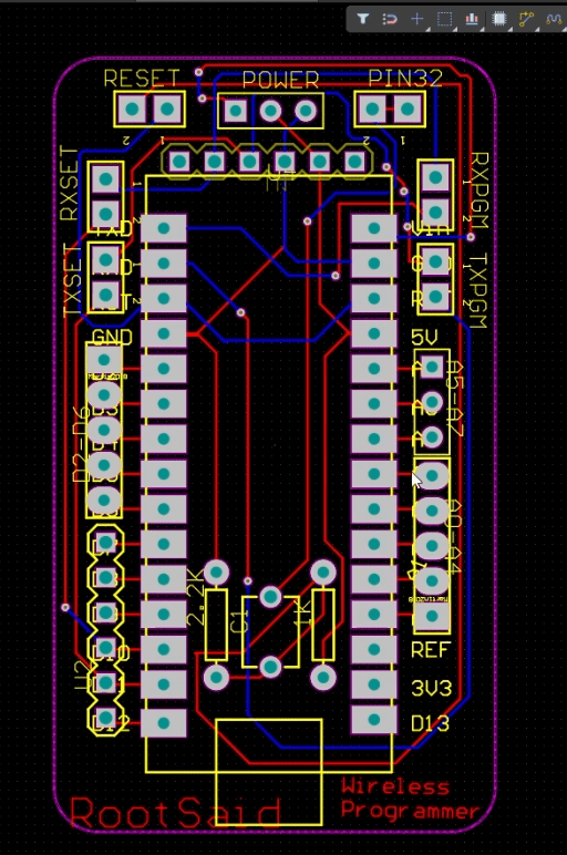
Then, using Altium, I designed a compact PCB on which I could neatly mount all of the components. Here, you can see that the board has routing on both sides, which means it’s a dual-layer PCB. All that’s left to do is export the Gerber file to your computer.
Setting up the PCB
PCBWay provided me with a PCB that I ordered. In addition to PCB prototyping, PCBWay specialises in PCB assembly and neat and tidy PCB assembly.

The PCBWay website has an instant order form that you can use to place an order. On the next page, you’ll be taken to a form where you can provide more detailed information about the board. The PCB specification screen allows you to update your board’s information. You should be able to upload your Gerber file and submit it for review on the next screen. As soon as the review is complete, you can add the PCBs to your shopping cart, pay for them and wait for them to arrive.
Soldering the components and the PCB together is the next step. Verify the polarity of the components before soldering them on the board.
Step 1 – Upload Baud Rate
In this case, the HC05 module is supposed to upload a code to Arduino when it receives a code from our laptop. For this, we must ensure that both the Arduino board and the Bluetooth module have the same baud rate. Each board has its own baud rate at which programmes are uploaded. Arduino Nano with Atmega328 operates at 57600 baud, while the Arduino Nano with Atmega168 operates at 19200 baud.
We send AT commands to the Bluetooth module in order to configure it. There are a number of ways to accomplish this. I decided to configure the Bluetooth module with an Arduino.
Step 2 – The Circuit
This is the circuit for configuration.
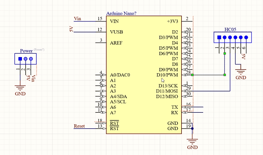
- HC05 GND to Arduino GND Pin
- HC05 5V to Arduino 5V
- HC05 TX to Arduino Digital Pin 10 (soft RX)
- HC05 RX to Arduino Digital Pin11 (soft TX)
If you are using this Shield, Simply connect the headers to RXSet and TXSet and you are good to go.
Step 3 – Putting the Bluetooth Module into Command Mode
The Bluetooth module must be connected to the PCB or breadboard after pressing this button. After two seconds, hold the key button down until the Bluetooth module LED begins blinking at a 2 second interval. While in command mode, the LED on the Bluetooth module blinks at a slower rate than when it is in regular mode.
Step 4 – Code Upload
In the next step, we’ll upload the code, and then open the serial monitor and begin sending AT commands.
#include <SoftwareSerial.h>
const byte HC12RxdPin = 10;// Recieve Pin on HC12
const byte HC12TxdPin = 11;// Transmit Pin on HC12

SoftwareSerial RSDBlue(HC12TxdPin, HC12RxdPin); // RX - 11 | TX - 10
void setup()
{

  Serial.begin(9600);
  RSDBlue.begin(38400);//Depends on your HC12 Module, Set Baudrate of Serial Monitor to 9600
  Serial.println("Starting Configuration..");
  Serial.println("Enter AT Commands : ");

}

void loop()
{
  if (RSDBlue.available())
    Serial.write(RSDBlue.read());

  if (Serial.available())
    RSDBlue.write(Serial.read());
}
AT
AT+ROLE=0
AT+NAME=RootSaid BT Module
AT+UART=57600,0,0
AT+POLAR=1,0The HC05 Module will receive these commands. At this point, you can remove all of the connections, which concludes Part 1.
Step 5 – The Circuit
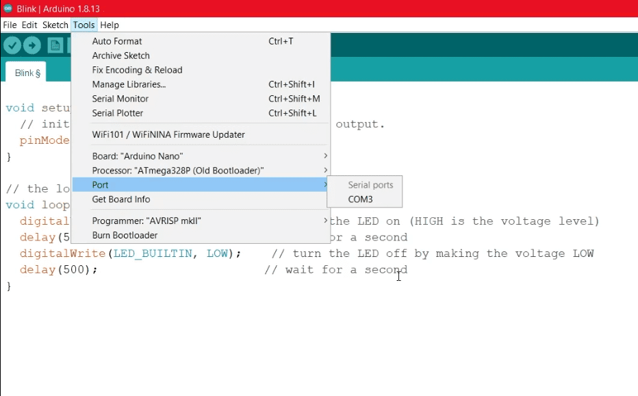
The schematic is shown here. Remove the headers from RXSet and TXSet and connect them to RXPGM, TXPGM, and RESET if you are using the Shield.Verify the COM Ports in the Arduino IDE.
Use the Arduino IDE and go to Tools>Ports. Take note of what you see there. We’ll need it to get by.
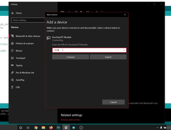
Step 6 – Pairing with the Bluetooth Module
Your laptop’s Bluetooth settings are now accessible, allowing you to scan for nearby devices. It should show you the Bluetooth module in the list of available modules. Set up a connection, enter a PIN, and pair the device.
Step 8 – Disconnect from PC
Battery or power bank can now be used to power the circuit. This USB cable will be used to connect it to the power bank. You should be aware that there is no connection between the board and the computer at any time.
Step 9 – Upload the code.
Guys, that’s all there is to it! All codes should now be able to be uploaded to the Arduino without a data cable.
![The Era of Crypto Gambling | What is Crypto Gaming? [Explained for Beginners]](https://hackersgrid.com/wp-content/uploads/2021/12/Crypto-Gaming-768x432.jpg)