Automatic Plant Watering System using Arduino Nano
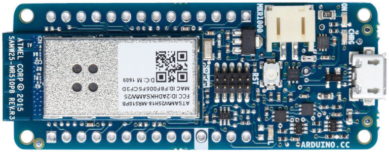
Lets make an IOT based plant watering system using Arduino Nano 33 IoT, some pumps and an Android Smart Phone.
Introduction
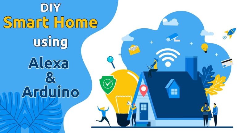
Home automation is a popular subject these days and with excellent cause. Our smart devices may be connected to the Internet and controlled remotely using an app or voice software. This implies that you won’t have to manually control them anymore when you want to adjust the thermostat, draw the curtains, or water your plants!
Advantages of IoT enabled Plant Watering System
One of the main benefits of using a smart irrigation system is that it can help conserve water. By watering plants at regular intervals, we can prevent them from becoming dehydrated and save valuable resources in the process. A well-watered plant is a healthy plant, and an IoT-enabled watering system can help ensure that your plants are getting the right amount of water at all times. This is especially important for outdoor plants that might not get regular attention.
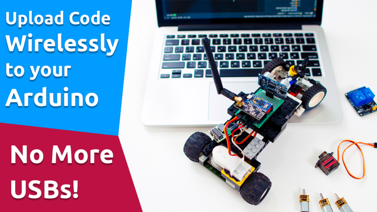
Perhaps the nicest part about utilizing an IoT-enabled irrigation system is that you can control it from anywhere if you have a connection to the internet. This means we may reap the benefits of this plant watering timer without having to water the plants manually before leaving for work on certain days, allowing us to focus on other tasks!
Circuit
So I used Altium Designer to draw the circuit and design the PCB. It is a powerful tool that can be used to design and create your own PCBs for your project as well as complex and multiplayer PCBs for industrial use.
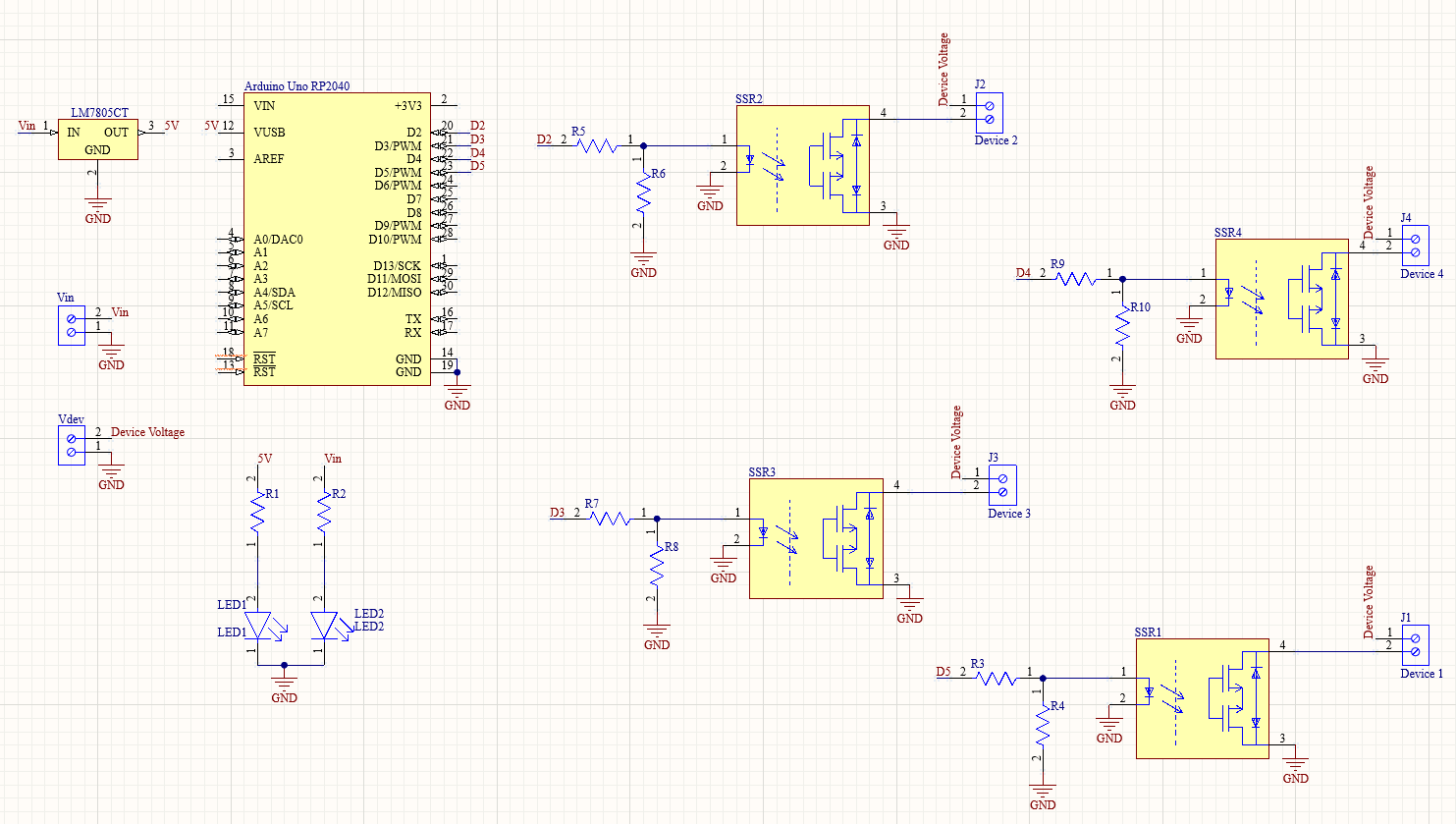
The board has two voltage inputs: one for the Arduino and other components, and another for driving the electronic devices connected to the relay, which will be controlled by an Android App.
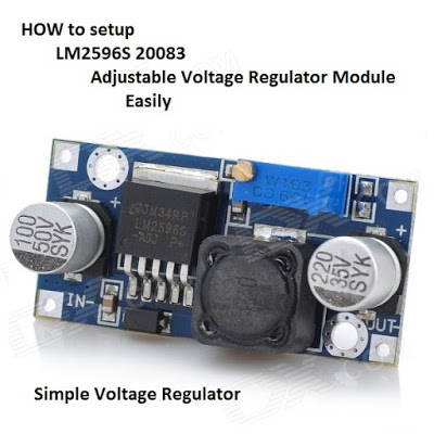
Here, I’ll be connecting a 12 V DC adapter to power the Pumps. A 7805 regulator is used to regulate the input voltage. The 7805 is a 5V regulator that converts an input voltage of 7-32V to a consistent 5V DC supply by using a 7-32V adjustable voltage conversion
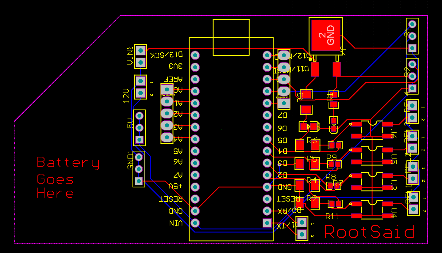
After the circuit was created and tested, I drew up a PCB layout for our watering system so I can simply mount your Arduino Nano 33 IOT and SSR, connect everything without having wires or cables hanging around. The board is compact and lightweight, and it may be run on a 9V battery or a 9-12 V power adapter.
Getting PCB Done
I ordered PCB from PCBWay. PCBWay is a PCB manufacturer specializing in PCB prototyping, low-volume production, and neat and tidy PCB assembly.

To order your PCB from PCBWay, go to the PCBWay website and fill in the basic board details in the instant order form. From there you will be directed to a form where you can provide more elaborate board details. Update your board information in the PCB specification screen. On the next screen, you should be able to upload your Gerber file and submit it for review. Once the review is completed, all that is left is to add to the cart, make payment, and wait for your PCBs to arrive.
Once you get all the components and the PCB, it’s time for you to solder them together. Solder all the components onto the board and make sure to check the polarity of the components. After soldering the PCB looks like this.
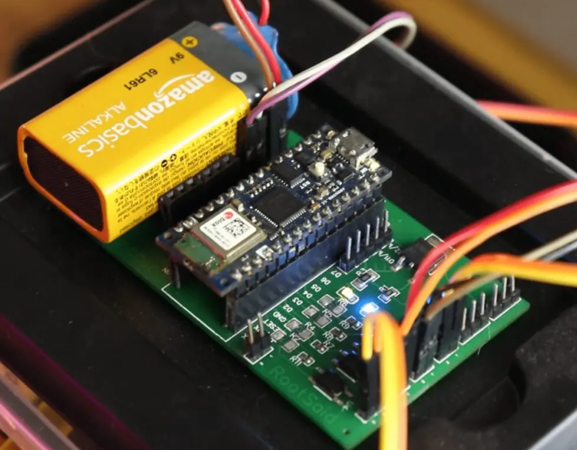
I personally find soldering on this kind of PCBs a fun task, because of these pads soldering becomes very easy. The solder takes up the conical shape and gets soldered from all the sides evenly. After soldering the PCB looks like this.
Step 2 – Download, Install, and Setup Arduino IDE
This tiny board may be readily programmed using the most user-friendly Open Source Platform – Arduino. This will be discussed in further detail. So, to start with, download and install the Arduino IDE from Here
Code
Let’s Take a look at the code –
#include <SPI.h>
#include <WiFiNINA.h>
#include <WiFiUdp.h>

int status = WL_IDLE_STATUS;
#include "arduino_secrets.h"
char ssid[] = SECRET_SSID;
char pass[] = SECRET_PASS;
int keyIndex = 0;
unsigned int localPort = 5005;

char packetBuffer[256];
char  ReplyBuffer[] = "acknowledged";

WiFiUDP Udp;

void setup() {
    pinMode(3, OUTPUT);
    pinMode(4, OUTPUT);
    pinMode(5, OUTPUT);
    pinMode(6, OUTPUT);
  Serial.begin(9600);
  while (!Serial) {
    ;
  }

  // check for the WiFi module:
  if (WiFi.status() == WL_NO_MODULE) {
    Serial.println("Communication with WiFi module failed!");
    // don't continue
    while (true);
  }

  String fv = WiFi.firmwareVersion();
  if (fv < WIFI_FIRMWARE_LATEST_VERSION) {
    Serial.println("Please upgrade the firmware");
  }

  // attempt to connect to Wifi network:
  while (status != WL_CONNECTED) {
    Serial.print("Attempting to connect to SSID: ");
    Serial.println(ssid);
    status = WiFi.begin(ssid, pass);

    delay(10000);
  }
  Serial.println("Connected to wifi");
  printWifiStatus();

  Serial.println("nStarting connection to server...");
  Udp.begin(localPort);
}

void loop() {

  int packetSize = Udp.parsePacket();
  if (packetSize) {
    //Serial.print("Received packet of size ");
    //Serial.println(packetSize);
    //Serial.print("From ");
    IPAddress remoteIp = Udp.remoteIP();
   // Serial.print(remoteIp);
   // Serial.print(", port ");
   // Serial.println(Udp.remotePort());

    int len = Udp.read(packetBuffer, 255);
    if (len > 0) {
      packetBuffer[len] = 0;
    }
    Serial.print("Command Received: ");
    Serial.println(packetBuffer);


 if(strcmp(packetBuffer, "device1on") == 0)
    {
       digitalWrite(3, HIGH);
       Serial.println("Turning Device 1 ON");

    }
 else if(strcmp(packetBuffer, "device1off") == 0)
    {
       digitalWrite(3, LOW);
       Serial.println("Turning Device 1 OFF");
    }
 else if(strcmp(packetBuffer, "device12on") == 0)
    {
       digitalWrite(4, HIGH);
       Serial.println("Turning Device 2 ON");
    }
 else if(strcmp(packetBuffer, "device2off") == 0)
    {
       digitalWrite(4, LOW);
       Serial.println("Turning Device 2 OFF");
    }
else if(strcmp(packetBuffer, "device3on") == 0)    {
       digitalWrite(5, HIGH);
       Serial.println("Turning Device 3 ON");
    }
else if(strcmp(packetBuffer, "device3off") == 0)    {
       digitalWrite(5, LOW);
       Serial.println("Turning Device 3 OFF");
    }
else if(strcmp(packetBuffer, "device4on") == 0)    {
       digitalWrite(6, HIGH);
       Serial.println("Turning Device 4 ON");
    }
else if(strcmp(packetBuffer, "device4off") == 0)    {
       digitalWrite(7, LOW);
       Serial.println("Turning Device 4 OFF");
    }

Serial.println("");
    Udp.beginPacket(Udp.remoteIP(), Udp.remotePort());
    Udp.write(ReplyBuffer);
    Udp.endPacket();
  }
}

void printWifiStatus() {
  // print the SSID of the network you're attached to:
  Serial.print("SSID: ");
  Serial.println(WiFi.SSID());

  // print your board's IP address:
  IPAddress ip = WiFi.localIP();
  Serial.print("IP Address: ");
  Serial.println(ip);

  // print the received signal strength:
  long rssi = WiFi.RSSI();
  Serial.print("signal strength (RSSI):");
  Serial.print(rssi);
  Serial.println(" dBm");
}
This is where you enter the ESSID and Passphrase of your network. Before uploading, make sure that you change values to SSID and Passphrase of your WiFi network.
This is the port, Arduino will be listening for incoming UDP packets, The 4 pins we will connect to the relay input, Here, we will connect to the WiFi network using predefined ESSID and Passphrase and set up a UDP listener in the predefined port, Save the UDP packet contents to the variable ‘packetBuffer’ and print its value. Turns the output of the pins to HIGH or LOW depending upon the packets received.
App
RootSaid WiFi Command Center is a simple lightweight android application that can be used to control robots and home devices using Raspberry Pi and Arduino over WiFi. All you have to do is connect your mobile phone to the network, enter the IP address and port of the server (the Arduino of our Home Automation system using Arduino) and control it using the On-Off buttons. Click here to know more about this App.
Click Here to Download this app from Playstore.
Testing!
Now all you have to do is start the app, enter the IP address of the Arduino and port it is listening to (5005). Load the IP and Port using the link button and navigate to the Home Automation Tab. Now, you should be able to turn on and off different pumps using the buttons.
You can now use this simple project to control pumps connected to your Arduino and turn it on and off.